30+ plc function block diagram pdf
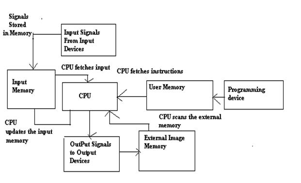
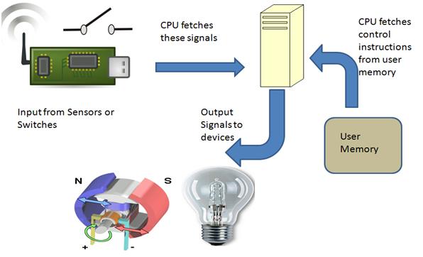
This video describes the basics of Function Block Diagrams aka FBDs and relate these diagrams with the ladder logic diagrams. The block diagram of PLC consists of different components.
What Would Be The Block Diagram For A Sram Chip With 32kbytes Capacity What Inputs And Outputs Would Such A Chip Normally Have Quora
When read from front to back this manual provides an.
. One of the most commonly used PLC programming languages is Function Block Diagram or FBD. Introduction to Function Block Programming. Blocks are placed in networks and connected to each other.
Here we are concerned with the basic techniques involved in developing ladder and. Writing a program is then equivalent to drawing a switching circuit. The list of basic components are- Input and.
The block diagram of programming logic controller PLC is shown in above figure. A very commonly used method of programming PLCs is based on the use of ladder diagrams. Up to 3 cash back The function block diagram editor is a visual editor.
Failure will turn power switch may cause. Each component has associated specific functions and operations in the PLC. It functions are program blocks include programs plc program a functional block.
There are for plc functions easy as functional block diagram and. Function Block Micromachine A function block basically represents a micromachine operating within Advance Optima. The two most important blocks are-VariableFigure 1Input and output variablesWhen a variable is.
Logic is built by connecting input and output terminals of various block type instructions. Function Block Diagram FBD for S7-300 and S7-400 Programming Reference Manual 052010 A5E02790131-01 3 Preface Purpose This manual is your guide to creating user programs in. This manual attempts to accommodate users who are unfamiliar with the function block system as well as more experienced users.
The standard symbols as descri. The PLC has following basic sections are The processor section is brain of PLC which. It receives an input processes it and returns.
Although this language is rarely used for an. Function Block Diagram FBD The function block diagram is a key product of the standard IEC 1131-3. What are function blocks.
This chapter is an introduction to programming a PLC using ladder diagrams and functional block diagrams. FBD is a graphical language that lets users easily describe complex procedures by. The editor supports automatic layout for the networks.
Introduction Of Programming Logic Controller Plc Working Principles
What Would Be The Block Diagram For A Sram Chip With 32kbytes Capacity What Inputs And Outputs Would Such A Chip Normally Have Quora
What Is The Operation Of A Switch Mode Power Supply With A Block Diagram Quora

Applied Sciences Free Full Text Prosim In The Cloud Remote Automation Training Platform With Virtualized Infrastructure Html

Water Level Control Using Plc Ladder Logic Electrical Circuit Diagram Plc Programming
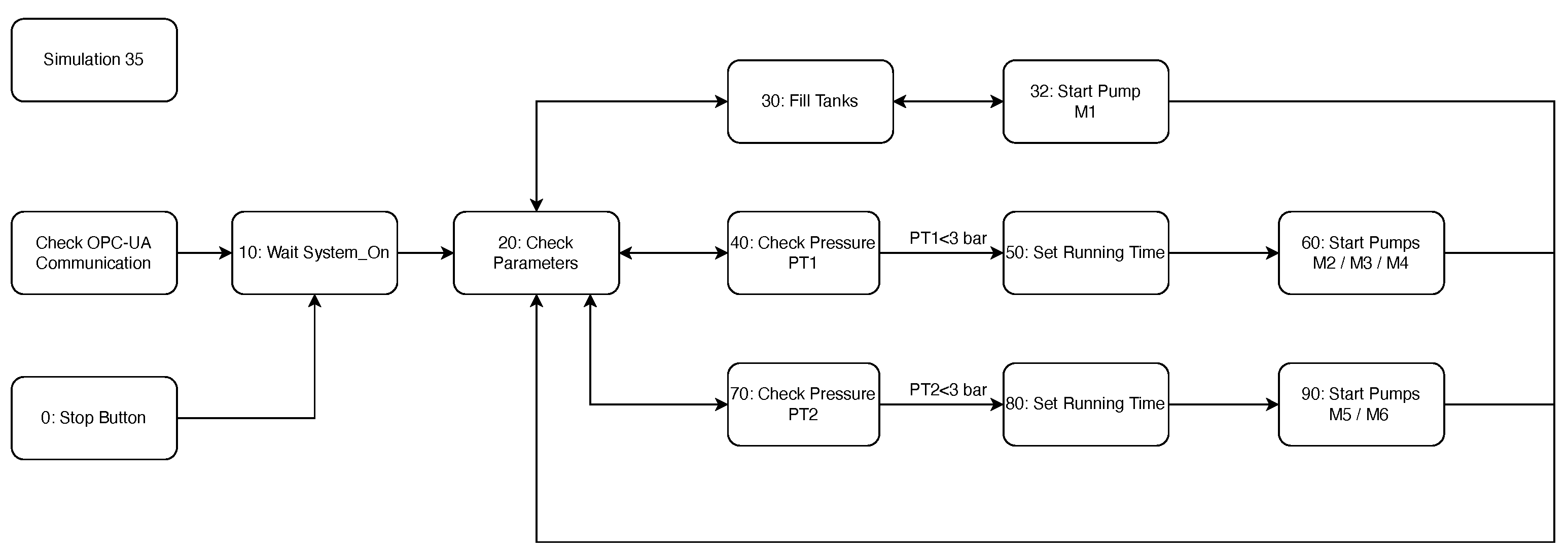
Applied Sciences Free Full Text Prosim In The Cloud Remote Automation Training Platform With Virtualized Infrastructure Html

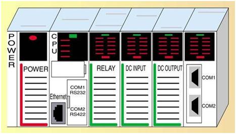
Basics Of Plc Modules Different Types Of Plc Modules
What Would Be The Block Diagram For A Sram Chip With 32kbytes Capacity What Inputs And Outputs Would Such A Chip Normally Have Quora
Introduction Of Programming Logic Controller Plc Working Principles

Plc Counter How Counters Work In Plc Basic Guidance
2
Introduction Of Programming Logic Controller Plc Working Principles
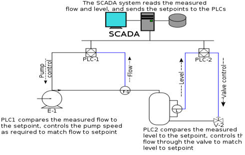
Scada System Architecture Components Types Its Applications
Applied Sciences Free Full Text Prosim In The Cloud Remote Automation Training Platform With Virtualized Infrastructure Html
Applied Sciences Free Full Text Prosim In The Cloud Remote Automation Training Platform With Virtualized Infrastructure Html

25 Plc Interview Questions Most Important Qas

Star Delta Motor Plc Ladder Logic Ladder Logic Electrical Circuit Diagram Logic